
Views: 0 Author: Site Editor Publish Time: 2026-08-10 Origin: Site


Urban and commercial lighting infrastructure relies on structural integrity, material science, and strict regulatory compliance. Engineers, urban planners, and procurement teams face a continuous challenge. You must balance material durability, environmental resilience against extreme wind loads, and municipal standards when sourcing or fabricating lighting structures. A failure in design or manufacturing compromises public safety and accelerates maintenance overhead.
This guide breaks down the complete progression of how to make a street light pole for industrial and municipal applications. We cover foundational design criteria, material selection, the industrial manufacturing process, and final site installation. By understanding the exact fabrication steps and engineering tolerances required, project managers and buyers can establish a rigorous technical framework for evaluating specifications and shortlisting qualified vendors.

Material dictates lifecycle: The choice between steel, aluminum, and composites fundamentally alters upfront costs, maintenance schedules, and structural longevity.
Compliance is non-negotiable: Manufacturing must align with AASHTO standards, local DOT approvals, and specific municipal setback requirements.
Manufacturing precision impacts yield strength: Processes like press braking, submerged arc welding, and hot-dip galvanizing are critical evaluation dimensions for vendor quality.
Foundation equals stability: Proper subgrade excavation, utility mapping, and anchor bolt casting are as vital to the street light pole's success as the fabrication of the shaft itself.
Table of Contents
A successful installation requires strict adherence to baseline structural requirements. The primary success criteria include structural safety under environmental stress, adequate illumination spread for pedestrian and vehicular traffic, and minimal maintenance overhead over a 20- to 30-year lifecycle. Engineers must match the shaft design to the specific luminaire weight and aerodynamics. A heavy cobra-head fixture placed on an undersized shaft creates dangerous deflection and metal fatigue. The structural geometry must account for the exact mounting height, the length of the mast arm, and the vibration harmonics generated by passing heavy vehicles.
Field experience shows that ignoring vibration harmonics leads to premature failure at the base plate weld. When heavy trucks pass, they generate low-frequency ground vibrations. The shaft acts as a tuning fork, amplifying these vibrations up to the luminaire. If the shaft lacks the proper wall thickness or dampening characteristics, the metal will eventually crack. You must specify vibration dampeners for installations near high-speed truck routes or railway lines.
Effective Projected Area (EPA) dictates the structural survival of any lighting installation. EPA represents the surface area of the luminaire, brackets, and mast arms that resist wind, multiplied by a drag coefficient based on their shape. Engineers calculate the total EPA to determine how much force the wind will exert on the top of the structure.
Local maximum wind speed ratings, often based on 50-year extreme weather data, directly dictate the required wall thickness (gauge) and yield strength of the shaft. Coastal regions experiencing hurricane-force winds require shafts with thicker walls, wider base plates, and higher-grade steel. Failing to match the maximum EPA rating with the combined EPA of the attached fixtures leads to catastrophic structural failure during severe weather events.
Fixture Type |
Typical EPA (sq. ft.) |
Drag Coefficient Factor |
Wind Load Impact |
|---|---|---|---|
Standard Cobra Head |
0.8 - 1.2 |
Low (Aerodynamic) |
Minimal deflection |
Shoebox / Area Light |
1.5 - 2.5 |
High (Flat surface) |
High torque on shaft |
Twin Bullhorn Bracket |
3.0 - 4.5 (Combined) |
Moderate |
Requires reinforced base |
Solar Panel Attachment |
5.0 - 8.0+ |
Very High |
Requires maximum gauge steel |
Commercial parking lots and wide highway intersections frequently require structures supporting multiple lights. These configurations utilize twin luminaires, bullhorn brackets, or heavy crossarms. Adding multiple fixtures exponentially increases the total EPA and shifts the center of gravity.
Engineering multi-arm setups requires reinforced shaft designs. Manufacturers increase the base diameter and utilize thicker steel gauges to handle the added torque. The base plate must also be upsized, utilizing larger anchor bolt circles to distribute the massive overturning moment into the concrete foundation. Symmetrical placement of luminaires helps balance the dead load, but the structure must still withstand asymmetrical wind gusts.
When specifying multi-arm configurations, you must account for the following structural modifications:
Increased Base Diameter: Expanding the base from a standard 4 inches to 6 or 8 inches to resist bending moments.
Thicker Wall Gauge: Upgrading from 11-gauge to 7-gauge or 3-gauge steel to prevent shaft buckling under heavy top loads.
Reinforced Tenon: Utilizing a thicker steel tenon at the top of the shaft to prevent the bullhorn bracket from snapping during high winds.
Expanded Bolt Circle: Increasing the anchor bolt circle diameter to spread the overturning forces across a wider area of the concrete foundation.
Municipalities enforce rigid design criteria to standardize city infrastructure and protect motorists. Minimum setbacks are strictly regulated. A common standard requires a mandatory three-foot setback, measured directly from the back of the curb to the center of the foundation. This setback prevents vehicle mirrors and bumpers from striking the structure while keeping the luminaire positioned correctly over the roadway.
Electrical safety standards dictate internal wiring protocols. Installers must leave a minimum of five feet of wire slack inside the base. This mandatory slack allows maintenance crews to safely pull the wiring through the handhole, splice connections, or replace internal fusing without straining the underground electrical feed. Failure to provide adequate slack results in failed municipal inspections and requires costly rewiring.

Steel remains the dominant material for highway and heavy commercial lighting infrastructure. High tensile strength and extreme durability make steel the ideal choice for high-wind areas and heavy multi-luminaire setups. Steel shafts can reach heights exceeding 50 feet while supporting massive high-mast lighting arrays. Standard fabrication utilizes ASTM A595 grade steel, which provides a minimum yield strength of 55,000 PSI.
The primary trade-off involves weight and corrosion management. Heavy steel increases shipping logistics and requires larger cranes for installation. Furthermore, raw steel rusts rapidly. It requires robust hot-dip galvanizing to coat the metal in a protective zinc layer. If the galvanizing is scratched or poorly applied, the structural integrity degrades rapidly over time. Maintenance crews must periodically inspect the base for rust, especially in areas where landscaping equipment might chip the protective coating.
Aluminum offers a distinct advantage in highly corrosive environments. It is naturally corrosion-resistant and exceptionally lightweight. Municipalities frequently deploy aluminum structures in coastal environments exposed to saltwater spray or in northern climates with high road-salt usage. The lighter weight simplifies installation, often allowing crews to erect the shaft without heavy crane equipment. Most manufacturers use 6063-T6 aluminum alloy, which provides an excellent balance of strength and extrudability.
However, aluminum carries a higher initial raw material cost. It also possesses a lower overall yield strength compared to carbon steel. This limits the maximum height and load capacity. Aluminum is generally restricted to pedestrian lighting, residential streets, and applications where the EPA remains relatively low. You cannot use standard aluminum shafts for high-mast highway lighting or heavy solar panel arrays.
Fiberglass and polymer composites provide a specialized alternative to traditional metals. These materials are entirely non-conductive, drastically improving electrical safety and eliminating the risk of stray voltage shocks to pedestrians. They carry zero corrosion risk and are remarkably lightweight. Installers can often carry and set a fiberglass shaft by hand, eliminating the need for heavy lifting equipment.
The trade-offs include susceptibility to UV degradation. Over long periods of intense sun exposure, untreated fiberglass can experience fiber bloom, where the surface degrades and exposes the internal glass strands. Proper UV-resistant polyurethane coatings are mandatory. Additionally, composites offer less aesthetic versatility and lower rigidity compared to steel. They will deflect and sway more noticeably in high winds, which can be distracting to motorists.
Material |
Yield Strength |
Corrosion Resistance |
Weight Profile |
Ideal Application |
|---|---|---|---|---|
Galvanized Steel |
Very High (Up to 65,000 PSI) |
Moderate (Requires Zinc Coating) |
Heavy |
Highways, High-Wind Zones, Multi-Arm |
Aluminum |
Moderate (Up to 35,000 PSI) |
Excellent (Natural Oxide Layer) |
Lightweight |
Coastal Areas, Pedestrian Walkways |
Fiberglass |
Low to Moderate |
Absolute (Non-metallic) |
Very Lightweight |
High-Corrosion Zones, Parks |
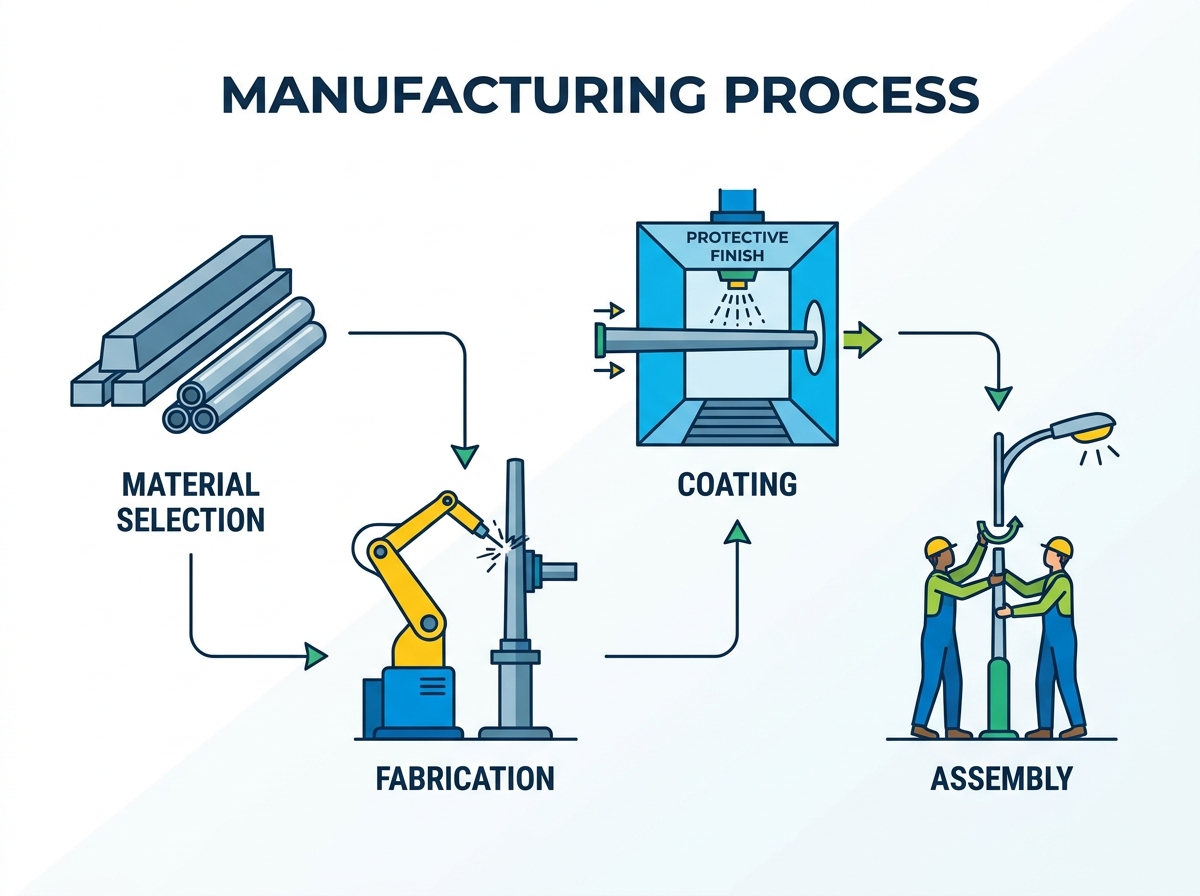
Industrial fabrication begins with sourcing industrial-grade steel or aluminum coils and heavy plates. Manufacturers unroll and flatten the metal coils using heavy leveling machines to remove any memory or curvature from the steel. Precision cutting is the next phase. Facilities utilize CNC plasma or laser cutting machines to slice the flat steel into exact trapezoidal shapes. This specific geometry is required to create the tapered design of the final shaft, ensuring a wider base that gradually narrows toward the luminaire mounting point.
The cutting tolerances must be exact. If the trapezoid is cut even a fraction of an inch off-center, the final shaft will twist during the forming process. Laser cutting provides the cleanest edge, which is necessary for a flawless longitudinal weld later in the process. Plasma cutting is faster but requires secondary grinding to remove dross and prepare the edge for welding.
Transforming flat metal into a rigid, three-dimensional shaft requires immense mechanical force. For polygonal designs, such as octagonal or dodecagonal shapes, manufacturers use massive hydraulic press brakes. The press brake bends the trapezoidal steel plate along precise longitudinal lines. The operator advances the steel through the machine, bending it incrementally until the two edges meet to form a closed polygonal tube. This process requires press brakes capable of exerting over 1,000 tons of force for heavy-gauge steel.
For seamless round designs, facilities often use metal spinning or extrusion processes. Spinning involves rotating a metal tube at high speeds while applying pressure with a roller to taper the material. The forming process inherently alters the stress points of the metal, requiring careful engineering to ensure the steel retains its required yield strength without cracking at the bend radii.
Closing the longitudinal seam of the formed shaft demands high-penetration welding. Manufacturers deploy automated submerged arc welding (SAW) machines. The shaft moves along a track while a robotic welding head deposits a continuous, uniform weld down the entire length of the seam. The SAW process covers the arc in a layer of granular flux, preventing atmospheric contamination and ensuring a deep, flawless weld.
Seam integrity is paramount. Facilities conduct rigorous non-destructive testing (NDT) on the welds. Technicians use ultrasonic testing or X-ray inspections to detect internal voids, slag inclusions, or incomplete penetration. A failed weld compromises the entire structure and must be ground out and re-welded. All welding procedures must comply with AWS D1.1 structural welding codes.
The base plate anchors the massive structure to the ground. It is cut from thick steel plate and features pre-drilled holes for the anchor bolts. Robotic welding cells attach the base plate to the bottom of the shaft, applying heavy fillet welds on both the inside and outside of the joint to handle extreme overturning forces. The base plate weld is the most highly stressed joint on the entire structure.
Next, technicians cut electrical openings, handholes, and internal conduit routing channels. Cutting a hole into the base of the shaft creates a localized weak point. To mitigate this, manufacturers weld a heavy steel reinforcing frame around the handhole. This frame restores the structural integrity lost by removing the metal and provides a secure mounting point for the access cover. The handhole must be positioned exactly 180 degrees opposite the luminaire arm to ensure proper weight distribution and access.
Bare steel rapidly degrades when exposed to the elements. The surface finishing phase provides the necessary environmental armor. The process begins with acid pickling, where the shaft is submerged in caustic solutions to strip away mill scale, rust, and oil. The steel must be completely bare for the zinc to adhere properly.
For steel, the shaft is then lowered into a massive vat of molten zinc at approximately 840°F (449°C). This hot-dip galvanizing process creates a metallurgical bond between the steel and the zinc, providing decades of rust protection. The galvanizing thickness must meet ASTM A123 standards, typically requiring a minimum of 3.0 mils of zinc coverage. For aesthetic purposes and secondary weather protection, manufacturers may apply a final powder coating. The powder is electrostatically applied and baked in an oven, creating a durable, chip-resistant colored finish over the galvanized layer.

Site preparation carries severe implementation risks. Striking underground high-voltage cables, fiber optics, or gas pipelines during digging causes catastrophic damage and project shutdowns. Mandatory utility locating and mapping must occur prior to any subgrade and foundation excavation. Crews utilize ground-penetrating radar and coordinate with local 811 services to mark all subterranean hazards.
Once cleared, heavy augers drill the foundation hole to the engineered depth, which often exceeds six feet depending on the soil composition and wind load requirements. In areas with dense underground utilities, crews use hydro-vacuum excavation. This method uses high-pressure water and a vacuum hose to safely remove dirt without damaging buried pipes or cables.
The foundation provides the necessary counterweight to the towering metal structure. Crews assemble a cylindrical rebar cage to reinforce the concrete. The anchor bolts are suspended at the top of this cage using a rigid wooden or steel template. This template perfectly matches the bolt circle of the base plate, ensuring exact alignment. The anchor bolts must project exactly the right distance above the concrete to accommodate the leveling nuts, the base plate, and the top securing nuts.
Concrete is poured into the excavated hole, encapsulating the rebar and the lower portion of the anchor bolts. Crews vibrate the concrete to remove air pockets and ensure a solid bond with the bolts. The foundation must undergo proper curing times before load-bearing. While initial set occurs quickly, crews typically wait at least 7 to 14 days before erecting the heavy structure to ensure the concrete has achieved sufficient compressive strength, usually a minimum of 3,000 PSI.
Installation requires precision rigging and heavy machinery. Crews use cranes or boom trucks to safely hoist the structure. Nylon slings wrap around the upper third of the shaft to maintain balance during the lift. The base plate is carefully lowered onto the exposed anchor bolts. You must never stand directly under the load during this phase.
Installers use a double-nut leveling system. Nuts placed beneath the base plate are adjusted to plumb the shaft perfectly vertical, while top nuts are tightened to secure the structure. Once plumbed, crews often pack non-shrink grout under the base plate to provide continuous support and keep rodents out. The electrical wiring process follows. Electricians route the underground feed through the conduit openings into the base. They establish strict grounding protocols, connecting the grounding wire to a dedicated lug welded inside the handhole. Finally, they verify the mandatory five feet of wire slack is present for future maintenance access.
Procurement teams must evaluate the balance between initial capital expenditure and long-term maintenance cycles. Selecting cheaper, thinly galvanized steel structures reduces the upfront project bid. However, these units often require premature replacement or expensive field-painting when the thin zinc layer fails and rust compromises the base.
Investing in premium aluminum, fiberglass, or heavily powder-coated galvanized steel increases the initial manufacturing and material costs. Yet, these premium options drastically extend the lifecycle durability. They eliminate the need for routine rust mitigation and structural inspections, ultimately preserving municipal budgets over a 30-year operational window. You must specify the exact galvanizing mil thickness and powder coat warranty in your procurement documents to prevent vendors from substituting inferior finishes.
Project timelines depend heavily on supply chain logistics. Standard, off-the-shelf round or square steel shafts offer rapid lead times and predictable shipping. Custom fabrication, involving specific tapers, unique multi-arm brackets, or specialized powder-coat colors, can extend lead times by several months. You must align your foundation pouring schedule with the confirmed delivery dates of the anchor bolts, which are usually shipped ahead of the main shafts.
Shipping heavy, oversized loads to the installation site requires careful logistical planning. Tapered shafts are bulky and require specialized flatbed transport with custom dunnage to prevent the metal from rubbing and destroying the galvanized or powder-coated finish during transit. Procurement teams must factor these freight requirements and unloading equipment rentals into the project schedule.
Sourcing reliable infrastructure requires strict vendor vetting. Buyers must demand specific certifications from manufacturers before approving shop drawings. Compliance with AASHTO (American Association of State Highway and Transportation Officials) standards for structural supports for highway signs, luminaires, and traffic signals is mandatory for any roadway project.
Furthermore, procurement teams should request certified mill test reports (MTRs) for all raw materials. MTRs prove the chemical composition and yield strength of the steel or aluminum used in the fabrication process. Vendors who cannot produce transparent load testing data, MTRs, or certified welding inspection reports introduce unacceptable liability into the project. Always require AWS D1.1 welding certificates for the facility fabricating your order.
Consult with a licensed structural engineer to perform site-specific wind load and EPA calculations before finalizing any design.
Request detailed specification sheets, certified mill test reports, and surface finish warranties from all shortlisted vendors.
Verify local municipal setback requirements and map underground utilities before scheduling any foundation excavation.
Mandate non-destructive testing (NDT) reports for all longitudinal seam welds on steel and aluminum orders.
For municipal, roadway, and commercial lighting projects, Dison Group brings more than 30 years of experience in street lighting and integrated outdoor lighting solutions. Established in 1994, the company operates a 47,000 m² manufacturing facility and produces light poles alongside LED street lights, solar street lights, and solar power systems, supporting projects that require coordinated pole and lighting equipment supply.
A: Commercial structures are primarily manufactured from carbon steel, aluminum, or fiberglass composites. Steel offers the highest yield strength for tall, high-wind applications but requires hot-dip galvanizing to prevent rust. Aluminum provides natural corrosion resistance and lighter weight. Fiberglass is non-conductive and highly resistant to harsh, corrosive environments.
A: Wind load ratings and Effective Projected Area (EPA) dictate the required structural strength. Engineers calculate the EPA of the luminaire and brackets. The shaft's wall thickness, base diameter, and material yield strength must be engineered to withstand the maximum local wind speeds acting against that specific EPA.
A: The process begins by cutting flat steel plates into trapezoidal shapes. Massive hydraulic press brakes bend the steel into a polygonal tube, or spinning machines form a round taper. Automated submerged arc welding closes the longitudinal seam. Finally, base plates are welded on, and the steel is hot-dip galvanized.
A: Multi-luminaire setups utilize bullhorn brackets or heavy crossarms mounted to the top of the shaft. Because multiple fixtures exponentially increase the total EPA and shift the center of gravity, the shaft must be manufactured with thicker steel gauges, a wider base diameter, and a reinforced base plate.
A: Foundation depth depends on the soil composition, frost line, and the engineered wind load requirements. Depths typically range from four to over ten feet. An auger drills the hole, and a rebar cage with anchor bolts is set before pouring high-strength concrete to stabilize the structure.
A: Municipalities generally require a minimum setback of three feet, measured from the back of the curb to the center of the foundation. This standard prevents vehicle bumpers and mirrors from striking the metal shaft while keeping the luminaire properly positioned over the roadway.


