Views: 0 Author: Site Editor Publish Time: 2026-08-10 Origin: Site
Specifying the correct height for a street light pole dictates pedestrian safety, vehicular visibility, and overall project viability. Relying on generic height estimates without conducting proper photometric and structural analyses leads to severe project risks. We see this constantly in the field: contractors guess the height, resulting in light trespass, dark spots, code violations, and structural failures under heavy wind loads.
This guide breaks down the technical evaluation criteria for selecting heights. We cover application-specific standards, photometric variables, material limitations, and procurement frameworks for municipal and commercial projects. You will learn how to match fixture elevation with light distribution and structural integrity. This ensures your lighting layouts meet rigorous safety mandates while simplifying long-term maintenance for the crews operating bucket trucks and lifts on the ground.
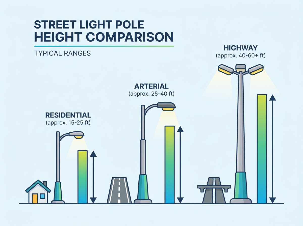
Application Dictates Baseline Height: Standard street light pole heights range from 9 to 14 feet for residential paths, 20 to 30 feet for urban roadways and parking lots, and 30 to 50+ feet for highways and high-mast applications.
Height and Spacing are Interdependent: The distance between poles must be calculated in direct proportion to pole height and fixture wattage to achieve uniform illumination without dark zones.
Structural Compliance is Non-Negotiable: Taller poles—and specialized applications like solar street lights—require rigorous Effective Projected Area (EPA) calculations to ensure the pole material, wall thickness, and foundation can withstand local wind load requirements.
Procurement Requires Holistic Evaluation: Selecting a street light pole requires balancing upfront material costs with long-term maintenance realities, such as the equipment needed to service fixtures at high elevations.
Table of Contents
Different environments demand specific mounting elevations to achieve target illumination levels safely. You must match the pole height to the speed of travel, the width of the target area, and the surrounding architectural context. Installing a highway pole in a residential neighborhood creates massive light trespass, while putting a pedestrian pole on a main arterial road leaves drivers in the dark.
Lighting in residential subdivisions and dedicated walking paths requires a strictly localized approach. Poles in these areas generally stand between 9 and 14 feet tall. This lower elevation keeps the light source closer to the ground, focusing illumination directly onto sidewalks and crossing areas where pedestrians need it most.
Minimize light trespass into nearby residential windows by utilizing lower mounting heights combined with house-side shields.
Scale the hardware for aesthetic integration, ensuring the infrastructure does not overwhelm the neighborhood landscape.
Maintain a high degree of vertical illuminance to help pedestrians recognize faces and potential obstacles from a safe distance.
Utilize direct burial fiberglass or light-duty anchor base aluminum poles to speed up installation without requiring heavy cranes.
Bicycle lanes and multi-use trails require slightly taller infrastructure than basic pedestrian paths. Cyclists travel at higher speeds, meaning they need a longer visual lead time to react to surface hazards, debris, or intersecting traffic. Poles ranging from 15 to 20 feet provide a wider spread of light along the trail.
Achieve a broader distribution footprint to illuminate potential hazards on the trail surface without blinding oncoming riders.
Ensure the height clears low-hanging tree branches that commonly line suburban multi-use trails.
Maintain consistent spacing to eliminate strobing effects, which disorient cyclists moving at speed through alternating bright and dark patches.
Municipal streets, downtown grids, and commercial intersections typically utilize poles between 20 and 30 feet tall. This height serves as the standard baseline for urban infrastructure. It provides enough elevation to cast light across two to four traffic lanes while remaining low enough for municipal crews to service easily with standard bucket trucks.
Optimize height to clear commercial storefront signage and urban tree canopies.
Pair these poles with 4-to-8 foot mounting mast arms to position the luminaire directly over the active traffic lanes.
Account for complex intersection geometries by utilizing taller poles within this range to support multiple fixture heads.
Ensure the luminaire mounting height provides at least 15 feet of vertical clearance to prevent strikes from passing box trucks and delivery vehicles.
Parking facilities require broad, uniform illumination to ensure driver and pedestrian safety. A standard height of approximately 26 feet (8 meters) allows a single pole to distribute light across multiple parking stalls and drive aisles effectively.
Balance wide area illumination with the strict need to minimize direct glare for drivers navigating tight parking rows.
Utilize quad-mount fixture configurations on a single central pole to maximize coverage square footage.
Keep perimeter poles slightly lower or heavily shielded to prevent light from spilling into adjacent properties or roadways.
Mount these poles on 30-inch raised concrete bases to protect the metal shaft from vehicle bumper impacts.
High-speed corridors demand highly engineered lighting solutions. Drivers moving at highway speeds require maximum reaction time, which translates to a need for wide, highly uniform light distribution. Poles in these applications range from 30 to 50 feet.
Reduce the total number of poles required per mile by leveraging taller heights, which allows for significantly wider spacing intervals.
Implement robust structural engineering to handle constant vibration from heavy freight traffic and continuous high wind exposure.
Utilize breakaway base designs mandated by transportation departments to minimize impact severity during vehicular collisions.
Position poles further back from the travel lane, using extended mast arms to achieve the necessary optical center.
Massive infrastructure projects, such as complex highway interchanges, shipping ports, and industrial rail yards, rely on high-mast lighting. These structures exceed 50 feet and can sometimes reach up to 150 feet.
Illuminate vast square footage using a single pole structure equipped with multiple high-lumen fixtures.
Incorporate specialized motorized lowering ring systems that allow maintenance crews to service the luminaires at ground level.
Weight foundation engineering heavily, as these massive structures require deep concrete caissons and massive anchor bolt cages to resist extreme overturning moments.
Application Type | Height Range (Feet) | Typical Fixture Wattage (LED) | Primary Material Suitability |
|---|---|---|---|
Residential Pathways | 9 – 14 ft | 30W – 50W | Aluminum, Fiberglass |
Bike Trails | 15 – 20 ft | 40W – 70W | Aluminum, Steel |
Urban Roadways | 20 – 30 ft | 80W – 150W | Steel, Aluminum, Concrete |
Commercial Parking Lots | 20 – 30 ft | 100W – 200W | Steel, Aluminum |
Highways & Expressways | 30 – 50 ft | 200W – 300W | Galvanized Steel |
High-Mast Interchanges | 50+ ft | 400W – 1000W+ | Heavy-Gauge Steel |
Selecting a height is never arbitrary. Lighting designers and civil engineers rely on a specific set of interrelated variables to determine the exact elevation required for a given site. You must evaluate roadway geometry, photometric output, and spacing limitations simultaneously.
The physical width of the target area directly influences how tall the structure must be. A standard engineering rule of thumb dictates that the height of the pole should generally be equal to or slightly greater than the width of the roadway being illuminated. If you place a 15-foot pole on a 40-foot wide street, the light will fail to reach the opposite curb, creating a dangerous dark zone.
Engineers evaluate the required transverse light distribution to match the road geometry. The Illuminating Engineering Society (IES) defines specific distribution patterns. Type II distribution is ideal for narrow, two-lane roads. Type III pushes light further across medium-width roadways. Type IV produces a semi-circular footprint for wide perimeters, and Type V offers a 360-degree circular distribution for intersections. The taller the pole, the wider these distribution patterns stretch across the pavement.
There is a direct, mathematical correlation between mounting height and the required lumen output of the fixture. As you raise the light source higher into the air, the light dissipates over a larger area before hitting the ground. Consequently, higher poles require significantly higher wattage fixtures to deliver the required foot-candles to the surface.
You must assess the impact of height on the uniformity ratio, which measures the average light level against the minimum light level in a given area. A taller pole with a high-lumen fixture generally improves uniformity by smoothing out hot spots directly under the luminaire. Pushing a low-wattage fixture too high results in unacceptable overall illumination levels, failing to meet basic safety codes.
Measure the physical width of the target illumination zone from curb to curb.
Determine the required foot-candle average based on local municipal safety codes and traffic speeds.
Select a preliminary pole height equal to or slightly greater than the roadway width.
Run a photometric simulation using IES files to verify the uniformity ratio across the grid.
Adjust the longitudinal spacing between poles to eliminate dark spots and hot spots.
Finalize the mounting arm length to ensure the luminaire sits directly over the target lanes.
You must calculate the longitudinal distance between poles based on their height. Standard spacing is typically 2.5 to 3 times the mounting height. For example, if you select a 30-foot pole, the optimal spacing between structures will likely fall between 75 and 90 feet.
Engineers constantly evaluate this trade-off. Taller poles allow for wider spacing, which reduces the total pole count on a project. Fewer poles mean less trenching, less wiring, and fewer concrete foundations. However, taller individual poles require thicker materials, larger anchor bolts, and higher-wattage luminaires. You must balance the layout density against the structural demands of taller infrastructure.
Pole Height | Multiplier | Estimated Spacing Distance |
|---|---|---|
15 ft | 2.5x – 3x | 37.5 ft – 45 ft |
20 ft | 2.5x – 3x | 50 ft – 60 ft |
30 ft | 2.5x – 3x | 75 ft – 90 ft |
40 ft | 2.5x – 3x | 100 ft – 120 ft |
Poles are rarely installed directly on the curb line. Civil guidelines mandate a specific setback distance—known as the clear zone—to protect motorists who veer off the roadway. When you push the pole base further back from the curb, you must compensate by utilizing longer mast arms to ensure the light center remains positioned correctly over the target lanes.
Extended mast arms, which range from 8 to 12 feet, act as levers. They place significant eccentric loads on the pole shaft. The taller the pole and the longer the arm, the greater the stress at the base plate. This dynamic directly impacts the structural load calculations and dictates the required wall thickness of the pole material.
As height increases, the physical forces acting on the pole multiply exponentially. The material you select must possess the necessary tensile strength and rigidity to handle these loads while surviving the local environmental conditions.
High tensile strength makes steel the default choice for highway, commercial, and high-mast applications. Steel can be fabricated to reach extreme heights without buckling under heavy wind loads or the weight of multiple heavy fixtures.
Evaluate wall thickness (gauge) requirements carefully as height increases. A 40-foot pole requires a much heavier 7-gauge wall compared to a 20-foot pole, which often uses 11-gauge steel, to prevent dangerous deflection.
Account for vibration dampening. Tall steel poles on highways require internal vibration dampeners to prevent harmonic resonance caused by wind and heavy truck traffic.
Mitigate corrosion risks. Steel is highly susceptible to rust. It requires hot-dip galvanization inside and out, or specialized powder coating, particularly in coastal regions or northern climates where road salt is prevalent.
Aluminum is naturally corrosion-resistant and significantly lighter than steel. This lighter weight lowers transportation logistics and reduces the heavy equipment needed during installation. Crews can often hand-set a 15-foot aluminum pole without needing a crane.
Utilize aluminum primarily for residential, pedestrian, and standard urban applications where heights remain under 30 feet.
Leverage aluminum in coastal environments where salt spray rapidly degrades standard steel infrastructure.
Recognize the structural limitations. Aluminum has lower rigidity compared to steel. It is restricted to shorter heights or geographical areas with lower maximum wind load requirements.
Alternative materials serve highly specific regional or technical needs where metal poles fall short.
Fiberglass is non-conductive, lightweight, and highly resistant to environmental degradation. It is ideal for coastal residential areas and park pathways, typically utilized in the 10 to 20-foot range using direct burial installation methods.
Concrete is extremely durable with minimal deflection under load. While heavy and difficult to transport, spun concrete poles offer exceptional longevity and are frequently used in specific municipal legacy grids or hurricane-prone coastal zones.
Engineering a lighting layout involves strict adherence to structural and environmental regulations. Failing to account for wind loads or local zoning ordinances results in catastrophic structural failure or mandated removal of the installed infrastructure.
The Effective Projected Area (EPA) is a calculation that defines how much wind resistance a fixture, mounting arm, and pole shaft generate. You must define the total EPA of all components attached to the top of the pole. Think of it as calculating the sail area of a boat.
Ensure the selected height and material can support this total EPA at the maximum local wind speed. The American Association of State Highway and Transportation Officials (AASHTO) provides strict guidelines for wind load calculations. A 30-foot pole designed for a 90 mph wind zone in the Midwest will fail if installed in a 150 mph hurricane zone in Florida. You must verify the pole's structural calculations against the specific wind map of the project location.
Wind Zone Speed | Typical Region | Impact on Pole Engineering |
|---|---|---|
90 mph | Inland / Midwest | Standard 11-gauge steel or standard aluminum is usually sufficient for poles under 30 feet. |
110 mph | Coastal / High Plains | Requires thicker 7-gauge steel, larger base plates, and upgraded anchor bolts. |
150 mph | Hurricane Zones (FL, Gulf) | Mandates heavy-duty steel, restricted heights, and massive concrete foundations. |
Integrating solar technology completely changes the structural physics of the pole. Solar panels and heavy battery enclosures drastically increase both the EPA and the top-weight of the structure. The flat surface of a solar panel acts like a sail, catching wind and transferring massive kinetic energy down the pole shaft to the base plate.
To compensate for this added wind load, solar applications require highly specific engineering. These poles require thicker gauge steel, larger base plates, and significantly larger foundation footings. Engineers restrict the maximum height of a solar pole compared to a traditional AC-powered pole to maintain structural stability during severe weather events.
As you increase pole height, you simultaneously increase the risk of light bleeding off-site into unintended areas. This is a major liability in mixed-use or residential zones.
Evaluate the BUG (Backlight, Uplight, Glare) ratings of the selected luminaire in direct relation to the mounting height. Taller poles project light further, meaning backlight easily trespasses into residential bedroom windows. Ensure proper optical control, internal louvers, and external shielding are specified if you are utilizing poles over 20 feet near property lines. Strict adherence to these optical controls prevents community complaints and zoning violations.
Never finalize a pole height without cross-referencing local jurisdictional mandates. Municipalities and state Departments of Transportation enforce strict rules regarding infrastructure dimensions.
Verify height restrictions with local zoning boards. Many suburban communities enforce strict height caps to preserve neighborhood aesthetics. Check DOT guidelines for clear zone requirements and breakaway base mandates. Ensure the selected height and fixture combination complies with local Dark Sky mandates, which strictly regulate uplight and color temperature to protect nocturnal environments.
Moving from engineering theory to actual procurement requires a structured approach. You must align your technical requirements with manufacturing realities to ensure the project remains viable, structurally sound, and easy to maintain over the next several decades.
Begin by establishing absolute baseline requirements. Define the target foot-candles required for safety, the maximum budget allocation for materials, and any strict aesthetic guidelines dictated by the city planner. Do not guess at heights or wattages. Require a comprehensive photometric layout from a qualified lighting designer or the OEM supplier before finalizing the pole height. This simulation proves mathematically that the chosen height delivers the exact light distribution required by the site geometry.
Custom manufacturing drastically increases lead times and material volume demands. To streamline procurement, specify heights based on standard OEM metric increments. The global manufacturing standard operates on specific metric lengths. Align your specifications with these standard increments: 6m (approximately 20 ft), 8m (approximately 26 ft), 10m (approximately 33 ft), 12m (approximately 40 ft), and 15m (approximately 50 ft). Utilizing these standard sizes ensures faster production, easier replacement part sourcing, and a more efficient supply chain.
Evaluate the physical footprint and maintenance demands of the structure. Taller poles generate massive overturning moments at the base, requiring deeper, wider, and highly engineered concrete footings. You must account for the soil conditions and the sheer volume of concrete required to anchor a 40-foot pole compared to a 20-foot pole. A 40-foot pole requires a massive rebar cage and 1-inch anchor bolts, whereas a 15-foot pole uses standard 3/4-inch hardware.
Assess maintenance accessibility early in the design phase. Poles under 30 feet are serviced by standard municipal bucket trucks. High-mast structures or poles exceeding 40 feet require specialized lift equipment, lane closures, or integrated mechanical lowering devices. You must ensure the local maintenance crews have the physical equipment necessary to reach the luminaires safely once the project is handed over.
Measure the exact curb-to-curb width of your roadway to establish the baseline minimum pole height.
Request a stamped photometric layout from your lighting engineer to verify fixture wattage and longitudinal spacing.
Calculate the total Effective Projected Area (EPA) of your selected luminaire and mast arm.
Cross-reference the total EPA against the local AASHTO wind load map to determine the required pole wall thickness.
Submit the final pole weight and base plate dimensions to a structural engineer to design the concrete foundation.
Established in 1994, Dison Group manufactures street lighting products, including LED and solar street lights, light poles, and related solar systems. With a 47,000-square-meter production facility and experience in municipal lighting projects, the company supports coordinated lighting and pole solutions for road, commercial, and public-space applications.
A: Residential poles typically range from 9 to 14 feet (3 to 4.5 meters). This lower height keeps the illumination focused on sidewalks and local streets while minimizing the risk of light trespassing into nearby bedroom windows.
A: Height and spacing are directly proportional. Taller poles allow light to spread further, meaning you can increase the longitudinal distance between each pole. Standard spacing is usually 2.5 to 3 times the mounting height.
A: Standard municipal street lights on major urban roadways generally max out around 30 to 40 feet. Heights above 50 feet are classified as high-mast lighting and are reserved for highways, interchanges, and large industrial facilities.
A: Engineers evaluate the total square footage, required foot-candles, and glare limits. A standard 26-foot (8-meter) pole is typically chosen because it provides wide coverage for multiple parking stalls without causing excessive glare for drivers.
A: Solar poles are often shorter or require much thicker steel than traditional poles. The large solar panels create a massive wind sail effect, limiting how tall the pole can safely be built without failing under wind loads.
A: Yes. Taller poles create significantly higher overturning moments at the base due to wind leverage. They require much deeper and wider reinforced concrete footings to prevent the structure from leaning or collapsing.