
Views: 0 Author: Site Editor Publish Time: 2026-08-10 Origin: Site


Commercial and municipal lighting projects operate under high stakes. Improper installation of a street light pole leads to catastrophic structural failures, severe liability, and costly rework. When you suspend hundreds of pounds of steel and luminaires over public walkways, you have zero margin for error. Facility managers, contractors, and municipal planners must bridge the gap between procuring hardware and executing a structurally sound, code-compliant installation. You have to navigate variable soil conditions, localized wind loads, and hidden underground utility risks before lifting a single piece of equipment. This guide provides a definitive, engineering-aligned framework for installation. We cover pre-excavation risk assessments, foundation pouring, rigging, and final luminaire leveling.

Site Preparation is Non-Negotiable: Locating underground utilities and assessing subgrade soil conditions dictate the structural requirements of the foundation.
Project Scoping Drives Hardware Selection: The surrounding environment, required pole height, and aesthetic appeal must be balanced with structural and photometric demands.
Foundation Precision Dictates Pole Lifespan: The accuracy of the anchor bolt template and concrete curing process directly impacts the plumbness and wind-resistance of the street light pole.
Rigging Requires Specialized Equipment: Safe erection relies on proper sling placement and load-rated lifting machinery (from cranes to portable installation machines) to protect the pole's finish, optimize crew time, and ensure operator safety.
Compliance and Leveling are Critical: Direct-buried wiring, junction box connections, and luminaire leveling must meet strict municipal specifications (e.g., AASHTO standards) to pass final inspection.
Table of Contents
Defining baseline requirements prevents dangerous accidents and structural compromises. You must establish necessary clearances, calculate structural load capacities, and verify local code adherence before breaking ground. Skipping these steps guarantees delays and failed inspections.
Determine the exact number of poles required by analyzing photometric layouts. A photometric plan ensures uniform light distribution across the target area. It eliminates dark spots and reduces glare. You must evaluate the surrounding environment to select the appropriate pole height and aesthetic appeal. This requires balancing architectural requirements with functional illumination needs. Historic districts often require decorative cast-iron or fluted aluminum poles. Highways demand tall, high-tensile steel structures for maximum light spread.
Review the photometric analysis to confirm spacing and mounting heights.
Identify potential physical obstructions like tree canopies or overhead power lines.
Select materials and finishes that match the municipal aesthetic guidelines.
Verify that the chosen height provides adequate illumination without causing light trespass into adjacent properties.
Map out the exact GPS coordinates for each foundation location.
Installing infrastructure along active roadways or in busy commercial parking lots requires strict traffic control measures. You must develop a site access plan that accommodates heavy machinery, concrete trucks, and crane outriggers without endangering the public. Implement a Maintenance of Traffic (MOT) plan that complies with the Manual on Uniform Traffic Control Devices (MUTCD). Deploy concrete barriers, directional signage, and flaggers to route vehicles away from the drop zone. Ensure the ground where the crane sets up is stable enough to support the outrigger pads. Soft asphalt or uncompacted soil will cause the crane to tip during a heavy lift.
You must utilize ground-penetrating radar (GPR) and local utility notification services like 811 before any subgrade excavation begins. Striking an underground gas line, fiber optic cable, or high-voltage conduit is a life-threatening error. Once utilities are marked and cleared, evaluate the soil composition. Cohesive soils like dense clay offer excellent bearing capacity. Cohesionless soils like loose sand or gravel require deeper, wider foundations to prevent the pole from leaning over time. Conduct a standard penetration test (SPT) if you suspect poor soil conditions. The blow count from the SPT gives the structural engineer the data needed to design a foundation that will not fail under heavy wind loads.
Wind load calculations dictate the physical survival of the structure. You must verify that the chosen street light pole and luminaire combination matches the local wind zone requirements. The Effective Projected Area (EPA) measures how much wind resistance the pole, luminaire, and any attached brackets or banners generate. High EPA values require stronger poles and more massive foundations.
Understand the trade-offs between pole height, material, and foundation requirements. Steel offers maximum strength for high-wind areas but requires heavy equipment to lift. Aluminum is lighter and highly corrosion-resistant but often requires vibration dampeners. Fiberglass is non-conductive and lightweight but has lower load capacities. Your foundation design must account for the specific material and the total EPA of the assembly.
Municipal engineers require comprehensive documentation before issuing permits. You must submit stamped structural drawings provided by a licensed professional engineer. These drawings detail the foundation design, anchor bolt specifications, and pole structural data. You will need to provide lighting distribution plans to prove compliance with local dark-sky ordinances and illumination standards. Ensure all paperwork aligns with AASHTO (American Association of State Highway and Transportation Officials) guidelines.

Comparing structural approaches for securing the pole ensures you choose the right method for your specific site conditions. The foundation anchors the entire system. A compromised foundation eventually leads to a leaning or collapsed pole.
The choice between an anchor base and a direct burial foundation depends on the pole material, soil conditions, and municipal preferences.
Feature |
Anchor Base Foundation |
Direct Burial Foundation |
|---|---|---|
Application |
High-wind areas, heavy commercial applications, steel and aluminum poles. |
Residential areas, parks, fiberglass or treated wood poles. |
Installation Speed |
Slower. Requires concrete pouring, curing time, and bolt alignment. |
Faster. Auger the hole, drop the pole, backfill, and tamp. |
Maintenance |
Easy access to base nuts for leveling. Pole can be replaced without digging. |
Difficult. Replacing a damaged pole requires full excavation. |
Structural Integrity |
Maximum rigidity and wind resistance when engineered correctly. |
Relies entirely on soil compaction and embedment depth. |
Concrete-poured foundations with anchor bolts are the standard for commercial and roadway lighting. They provide superior strength and allow for precise leveling. Direct burial is reserved for embedded poles where installation speed takes priority over long-term maintenance access.
You must strictly follow engineering parameters for foundation excavation. A standard rule of thumb for foundation depth is 10% of the pole height plus two feet. Soil EPA and local codes heavily modify this baseline. The foundation requires a properly tied rebar cage to provide tensile strength to the concrete. Concrete PSI requirements typically range from 3,000 to 4,000 PSI, depending on the structural engineer's specifications.
The rebar cage must maintain a minimum clearance from the edge of the excavated hole, typically three inches, to ensure the steel is fully encapsulated by concrete. This prevents groundwater from reaching the rebar and causing internal rust, which leads to concrete spalling. Prior to the concrete pour, route PVC electrical conduit through the center of the rebar cage. The conduit must extend above the finished concrete grade to allow for easy wire pulling into the pole base. Secure the conduit firmly so it does not shift during the heavy concrete pour. Vibrate the concrete as it is poured to eliminate air pockets and ensure a solid, monolithic structure. Allow the concrete to cure for a minimum of 7 to 14 days before subjecting it to the heavy wind loads of a fully rigged pole.
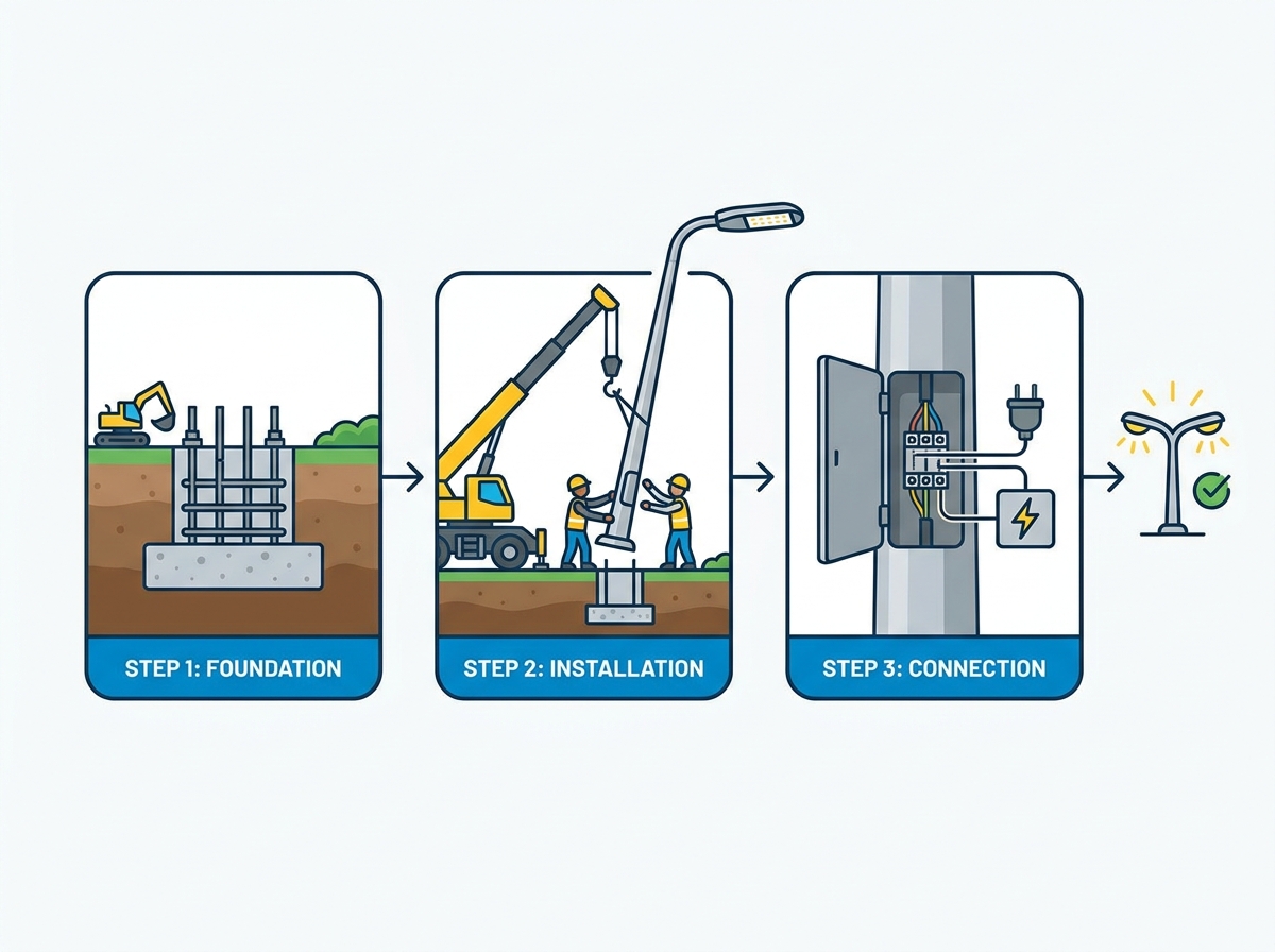
Moving from a poured foundation to a standing structure requires a chronological, highly technical execution framework. Precision during these phases prevents dangerous accidents and ensures the pole stands perfectly plumb.
The anchor bolt template ensures the bolts match the base plate of the street light pole exactly. Cut and position the template and template supports accurately over the excavated hole. Layout and drill your bolt pattern into the wooden template if it was not provided pre-drilled by the manufacturer.
Secure the bolts to the template using nuts and washers. The bolts must project at the exact height specified by the pole manufacturer. If they project too high, the base cover will not fit. If they are too low, you lack enough thread engagement for the leveling nuts and top nuts. Ensure the entire template assembly is perfectly level before and during the concrete pour. Once the concrete cures, removing or adjusting these bolts is incredibly difficult.
Attaching components while the pole is on the ground significantly improves safety and efficiency. Working at height in a bucket truck introduces unnecessary risk and slows down the installation. Rest the pole securely on heavy-duty sawhorses or wooden cribbing.
Unpack and inspect the luminaire housing for any shipping damage.
Attach post-top or cobra-head luminaires to the mast arms.
Secure the mast arms to the pole shaft using the manufacturer's specified torque values.
Pull the internal wiring from the luminaire down to the handhole at the base of the pole using a heavy-duty fish tape.
Leave at least three feet of slack wire at the base to allow the electrician to make comfortable, secure connections.
Support the wire weight inside the pole using a strain relief grip at the top to prevent the connections from pulling apart.
Install any required photocells or smart lighting control nodes.
Inspect all hardware and weather seals before the lift.
Lifting a commercial light pole is highly labor-intensive. A standard installation typically requires a three-to-four person crew and takes approximately one hour per pole without optimized equipment. You must use load-rated lifting machinery. Traditional cranes and bucket trucks with jibs are common. Specialized portable light pole installation machines reduce crew size and operator fatigue.
Attach a synthetic nylon sling to the top third of the pole. This placement ensures a balanced center of gravity during the lift, keeping the base heavy so it naturally points downward. Never use steel chains or wire ropes directly on the pole shaft. They crush the material and destroy the protective powder-coat finish. Attach a tagline to the base of the pole. One crew member must control the tagline to prevent the pole from swinging wildly in the wind as the crane lifts it into position.
As the crane operator lowers the pole, the ground crew guides the pole base plate over the anchor bolts. This requires careful coordination to avoid damaging the anchor bolt threads. Once the base plate rests on the leveling nuts, thread the top nuts onto the bolts to secure the structure.
Use the leveling nuts and washers underneath the base plate to achieve perfect plumbness. Place a high-quality magnetic level on the pole shaft, checking two sides that are 90 degrees apart. Adjust the bottom leveling nuts until the bubble is perfectly centered. Once plumb, execute a torque-tightening sequence for the top nuts. Use a star pattern—tightening opposite nuts sequentially—to ensure even pressure across the base plate. Verify the final torque against the manufacturer's specifications.
After the pole is plumbed and torqued, address the gap between the concrete foundation and the base plate. Install a galvanized wire mesh screen around the base gap to prevent rodents from nesting inside the pole and chewing through the electrical wires. Alternatively, dry-pack the void with non-shrink grout. If you use grout, you must leave a small weep hole at the lowest point. This weep hole allows internal condensation to drain out. Trapped moisture inside the pole base accelerates internal corrosion and destroys the grounding connections.

Ensuring the electrical components meet safety standards and operational longevity is just as important as the structural erection. Faulty wiring causes premature luminaire failure and poses severe shock hazards.
Routing wire from the junction box to the pole base must comply with the National Electrical Code (NEC). Evaluate whether your site requires direct-buried cables or conduit-protected wiring. Conduit provides superior protection against soil shifting, moisture, and rodent damage. Pull the supply wires up through the PVC conduit in the foundation and out through the pole's handhole.
Proper grounding techniques at the pole base are mandatory to mitigate electrical faults and lightning risks. Connect the ground wire to the dedicated grounding lug located inside the pole near the handhole. In many jurisdictions, a separate copper grounding rod must be driven into the earth adjacent to the foundation and bonded to the pole. Ensure all wire splices are made using waterproof, gel-filled wire nuts or submersible splice kits to prevent moisture ingress.
Install inline breakaway fuses inside the pole handhole for every hot leg of the electrical supply. If a vehicle strikes the pole and knocks it over, the breakaway fuses instantly disconnect the power. This prevents live wires from whipping around the crash site and electrocuting bystanders or first responders. Size the fuses according to the luminaire's amperage draw and the manufacturer's recommendations.
Once the pole is energized, inspect the luminaires. Head-type and post-top luminaires must be securely fastened and optically leveled. An improperly leveled luminaire causes light pollution, directing glare into nearby windows or blinding oncoming drivers. It disrupts the photometric plan, leaving dark patches on the ground. Use the internal leveling steps inside the luminaire housing to make micro-adjustments. Verify that all access doors and weather seals are tightly closed to prevent water and insect intrusion.
Identifying common failure points in street light pole installation allows you to engineer them out before they cause damage. Risk management is a continuous process throughout the installation.
Anchor bolts shift during the concrete pour if the template is not secured properly. If you discover misaligned bolts after the concrete has cured, you face a serious structural dilemma. The safest technical solution is using engineered adapter plates designed by a structural engineer to bridge the gap between the bolt pattern and the base plate.
You must strictly avoid unsafe practices like heating and bending the anchor bolts or torch-cutting the pole's base plate to make it fit. Bending bolts destroys their tensile strength. Cutting the base plate voids the manufacturer's warranty and compromises the pole's structural integrity. The trade-off is stark. You must weigh the cost of pouring a new foundation against the massive structural liability of a compromised base.
Lighter aluminum poles installed in high-wind, open-terrain environments are highly susceptible to Aeolian vibration. This high-frequency, low-amplitude vibration is caused by steady crosswinds shedding vortices around the cylindrical shaft. Over time, this vibration causes metal fatigue, leading to cracks at the weld line just above the base plate.
To mitigate this, install internal vibration dampeners. These devices are suspended inside the pole shaft and absorb the kinetic energy generated by the wind. First-mode dampeners handle swaying. Second-mode dampeners mitigate the destructive harmonic vibrations. Always consult the pole manufacturer to determine if your specific location and pole type require dampening. Inspect the weld line where the pole shaft meets the base plate regularly. Look for hairline cracks in the powder coating, which indicate underlying metal fatigue.
Galvanic corrosion occurs when dissimilar metals come into contact in the presence of an electrolyte, such as moisture or road salt. If an aluminum pole is bolted directly to steel anchor bolts without protection, the aluminum rapidly corrodes. Base-level rust and corrosion eventually cause the pole to collapse.
Use non-conductive shims between the base plate and the leveling nuts.
Apply anti-seize compounds to the anchor bolt threads.
Dry-pack non-shrink grout under the base plate to protect the bolts from moisture.
Ensure proper drainage pathways are left open in the grout so condensation inside the pole can escape.
Inspect the powder coating or galvanization for scratches and touch them up immediately with zinc-rich paint.
Establish a strict post-installation maintenance schedule to inspect the structural integrity of the pole base and luminaire housing annually.
Execute a mandatory 30-day torque check on all anchor bolts, as they often settle and loosen after initial wind loading.
Perform a baseline photometric inspection at night to verify that the light distribution matches the original engineering designs and eliminates dark spots.
Document all grounding resistance readings and keep the stamped structural drawings on file for future maintenance reference.
Founded in 1994, Dison Group develops and manufactures solar street lights, LED outdoor lighting, and light poles for municipal and commercial projects. Its integrated lighting and pole capabilities help buyers coordinate pole specifications, luminaires, structural requirements, and installation needs within one project supply plan.
A: The general rule of thumb for foundation depth is 10% of the pole's total height plus an additional 2 feet. This depth heavily depends on the soil's bearing capacity, the effective projected area (EPA) of the pole and luminaire, and local municipal building codes. A licensed structural engineer must dictate the final excavation depth based on site-specific soil testing.
A: To achieve uniform light distribution without dark spots, standard spacing is typically 2.5 to 3 times the mounting height of the luminaire. Poles with a 30-foot mounting height are generally spaced 75 to 90 feet apart. This ratio changes depending on the specific optics, wattage of the fixtures used, and the target foot-candle requirements of the roadway or parking lot.
A: Misaligned anchor bolts require engineered adapter plates or approved epoxy retrofits designed by a structural engineer. You must explicitly avoid heating and bending the bolts. Heating destroys their tensile strength and creates a massive liability. Modifying the pole's base plate with a cutting torch is also strictly prohibited and voids all manufacturer warranties.
A: Yes. Strict adherence to NEC grounding requirements is mandatory. Street light poles must be grounded to mitigate electrical faults and lightning strikes. You connect the equipment ground wire to a grounding lug inside the pole base. Many jurisdictions also require driving a dedicated copper grounding rod into the earth adjacent to the foundation and bonding it directly to the pole.
A: Lifting requires load-rated machinery such as cranes, bucket trucks with jibs, or specialized portable light pole installation machines. Your rigging gear must include synthetic nylon slings to protect the pole's powder-coat finish. You also need heavy-duty taglines attached to the base to stabilize the structure and prevent dangerous swinging during the overhead lift.
A: Excluding the time required for foundation excavation and concrete curing, the physical lift, rigging, and bolting process takes a standard three-to-four person crew about one hour per pole. Using specialized portable installation machines reduces this time and lowers the required crew size, significantly improving daily production rates on large municipal projects.
A: Direct burial is typically reserved for fiberglass, treated wood, or specially coated aluminum poles. Standard steel poles require an anchor base foundation mounted above grade. Burying standard steel directly in the dirt causes rapid soil-induced corrosion and moisture damage at the embedment line, eventually leading to structural failure and collapse.


